 This page will describe how to connect and control a relay or other switch
based device from the parallel port of your computer. This can be used for
a cheap homebrewed home automation solution for turning on and off lights, or
for using a computer to operate and/or replace a switch or button in some
other conventional appliance. This page will describe how to connect and control a relay or other switch
based device from the parallel port of your computer. This can be used for
a cheap homebrewed home automation solution for turning on and off lights, or
for using a computer to operate and/or replace a switch or button in some
other conventional appliance.
 Be advised that while
creating your own interfaces for your computer, there are some hazards you
should be aware of. First off, if your circuitry is not designed properly,
you may cause damage to your computer equipment. If you don't have a basic
working knowledge of how various electronic components work and how to
properly connect them together, please do whatever is necessary to gain
that education BEFORE experimenting with devices that might harm your computer.
It's also a good idea, for experimental purposes, to utilize older hardware,
as you can likely dig out of a dumpster equipment that is far in excess of
anything you will require. Be advised that while
creating your own interfaces for your computer, there are some hazards you
should be aware of. First off, if your circuitry is not designed properly,
you may cause damage to your computer equipment. If you don't have a basic
working knowledge of how various electronic components work and how to
properly connect them together, please do whatever is necessary to gain
that education BEFORE experimenting with devices that might harm your computer.
It's also a good idea, for experimental purposes, to utilize older hardware,
as you can likely dig out of a dumpster equipment that is far in excess of
anything you will require.
Also be advised, if you're
working with relays to control lights that operate off of a conventional
AC power source of sufficient voltage (such as that provided by a power
outlet), the voltage and amperage levels are extremely dangerous. Not only
is there the risk of electric shock, but if the wiring in use is insufficiently
small for the load you are working with, there is a fire hazard as well.
Please be sure to test all circuitry for faults before plugging it into
a wall socket. The testing process will be detailed later in this document.
Step 1: How this works
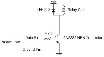
Refer to the schematic above. The heart of this circuit is the transistor.
The transistor acts like a simple electronic switch. When a small amount of
current is applied across the base and emitter contacts on the transistor,
it creates a change in the semiconductor state which allows an even larger
amount of current to pass between the collector and emitter contacts.
Therefore, to activate the "switch", you apply voltage to the base. This
voltage is provided by the 5V output from the parallel port data pin.
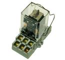
When the transistor will allow current to pass through, it can be used to
complete a circuit, such as that including the coil of a relay. This will
cause the relay contacts to close (or open), completing another circuit,
such as a connection between a lightbulb and your power outlet. Note that
the transistor (which passes only DC current, and only a small amount that that)
cannot handle the power needed to operate a conventional appliance. Likewise,
the data pin of a parallel port isn't sufficient to operate the coil of the
relay. The purpose of this circuit is to amplify the power applied at each
stage so an extremely small amount of power can control a much larger amount.
Step 2: Designing the circuit
The purpose of the transistor and relay have already been discussed. The
remaining components are important as well. First off, we have a 4.7k
resistor between the parallel port and the base of the 2N2222 transistor. This
limits the amount of current that the parallel port will sink. The diode
between the two contacts of the relay coil is also important. The coil is
an inductor. It will act like any other conductor except during two critical
moments. The moment power is applied to it, it will hold a small charge
of current. It takes a few milliseconds to fully absorb that current. When
the power supply is removed, the coil will discharge back into the circuit that
supplied the power. By placing a diode across the coils, that will be the
source of the sudden spike of voltage that will result from the coil suddenly
losing its power source. The diode will have no problem handling that surge
of current. However, other components in your circuit would not fare as well,
such as the transistor, and especially your parallel port.
For the especially paranoid among you can also include an optoisolator between
the data pin and the base of the transistor. This will ensure that anything
that goes wrong on the relay side of the circuit will not affect the
computer.
The Vdd power source requirement will depend on what your relay coil needs to
switch. If you have a 12V DC relay, you need a 12V DC source of power for this
part of the circuit. This can be a battery, a universal power supply,
or depending on the type of application, you can even use your PC's power
supply. Keep in mind, relay coils can use a number of different voltages,
so choose whatever makes the most sense for your application.
On the contact side of the relay, where you connect your actual appliance,
the voltage of the appliance makes no difference. At this point, we're just
talking a regular power switch. What we're concerned about now is the
amperage rating of the relay. A sugar cube sized relay can handle about 10
amps of current. One that fits in the palm of your hand will handle 15-30
amps. That usually exceeds the breaker size of a single house circuit, so
a single relay can easily handle quite a bit of power. However, for safety
and heat concerns, you should probably oversize your relay for the application
you intend to apply it to, and add fuses if you plan to deal with more than
an amp of current.
Step 3: Assembling the Circuit
If this is just an experiment, feel free to use a breadboard or other
prototyping system to build your circuit. Provided you use the right
components in the correct configuration, you will have no problem with either
a breadboard or soldered solution. However, keep in mind, on the
appliance side of the relay, The gauge of your wires need to be correctly
sized for your application. They can never be too large, but if they're
too small for the current requirements, they will get hot during use. This
can cause the insulation on the wires to melt, therefore causign a shock
and/or fire hazard. If possible, for any appliance that uses power from
a wall outlet, use at least 16 gauge wire, if not larger. If part of the
circuit on the appliance side of the relay uses copper traces, be certain that
the trace size is large enough to handle the current and that those traces
are protected from accidental human contact. The typical trace size on a
generic pre-traced pcb will handle about 2 amps at most. If you make your
own pcboards or have them custom printed, be sure to include large traces for
any part of the circuit that will handle a large current. Remember, too much
is better than not enough.
Step 4: Testing the Circuit
As mentioned earlier, there is the possibility for undesired consequences
for an improperly constructed circuit. Therefore, it's important to be
sure to test each part of the circuit before implementing it in a
potentially dangerous way. Take your trusty ohm meter, and make sure IT
works. Set it to measure resistance and make sure you get 0 resistance on a
direct connection between both probes.
Next, test the connection between the connection to the data pin and the
ground pin. There will be a measureable amount of resistance, but not an
absolute amount. However, if you have no resistance, that means you've got a
short between the two connections. Next, test the connection between the data
pin and the collector side of the emitter. Also ensure that power flows in
both directions across the relay coil (to test the diode). Next make sure that
both contacts of the appliance side of the relay have no electrical connection
to any other part of the circuit. If they are not absolutely electrically
isolated, you have a problem.
Step 5: Programming the Circuit
Controlling the data pins on the parallel port is easy enough, but how you
do so will depend on the language and operating system that you are planning
to use. Sample source for several different languages and
platforms will be included here at a later date. Note that getting the relay to turn on and off
is just the beginning. You'll likely require more programming to perform
your desired application.
Step 6: Let there be Light!
Now the fun part, connect everything up, run your program and turn the light
on and off. Of course, once the novelty of a flashing light has worn off,
you'll want to consider other possibilities. Keep in mind, the transistor
doesn't have to be connected to a relay. It can drive a simple LED or in
the case of a small DC lamp, you could connect that in line with the transistor
and bypass the relay. In this case, since you wouldn't have a coil absorbing
current, you wouldn't require an opposing diode, but you will want to add
a resistor in line with the lamp to prevent overheating. Use ohms law to
determine what size of a resistor you'll need depending on the resistace of
the lamp.
Since you effectively have a switch replacement, either the relay or the
transistor can replace or work in parallel to a switch in any other appliance.
Say you have a small toy that operates by the push of a button. That button
will be connected to the circuitry of the toy by two wires (as you would
expect). Extract the button and connect those wires instead to the relay
contacts, and you can now activate the toy by simulating a button push with
your software.
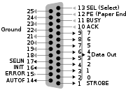
Also, there are 8 data pins on the parallel port, and an additional 5 pins
you can use for this purpose as well, although there will be logic and
programming differences to use them. Each pin requires a complete circuit
identical to the first one, although they all share the same common ground
and can all share the same 12V relay power source.
|
Parallel Port Pinout
|