|
This page describes the project known as The Critter which is a
homebrewed robot platform with its own computer and cam on board that uses
802.11b for the communication of commands, telemetry, and video, all
controllable and viewable via the internet. Stage 1 of this project is
getting a simple prototype functional. I consider that stage complete.
I shall detail the development of the project up to this point and future
plans.
Introduction
First, let me describe my goals with this project, which is by no means
complete, hence the Stage 1 in the title. In the past I've had
several remote controlled vehicles, all of which were cool and fun, but
severely lacking in rather annoying ways. The various problems I've had
have been harped on extensively in other forums, so I won't go into them
here. However, the primary goals have come about as a result of those
past annoyances. They are as follows:
- A platform large enough, and sturdy enough to carry enough weight to
support a battery capable of operating the unit at normal usage for a minimum of 12 hours
without a recharge.
- Stable enough to tilt up to 30 degrees in any direction without losing balance and with the drive wheels maintaining contact with the ground.
- A communications medium that easily covers the desired playground, with sufficient onboard programming to troubleshoot a loss of signal and manuver to
reaquire.
- Sufficient proximity sensors to avoid any accidental or even intentional
contact with walls, furniture, or other objects, and also to prevent the
critter from going under or in between any objects without enough clearance to manuver.
- Robust enough to handle a signficiant amount of abuse as the sensors can't be 100% efficient
- The ability to locate itself on a previously created map and navigate from one point on the map to another autonomously
- Capability to locate, dock with, and engage one or more charging stations
- A powerful and accurate drivetrain with odometry and minimal friction
issues.
- Cost effective. First off, I'm not made of money, so I don't want to spend TOO much on this project. Secondly, I want to aim toward making this into a project that I could market and sell, so I would need to be able to construct it
inexpensively enough to be able to sell it at a price people are willing
to buy it at.
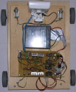
Gathering the Components
Computer
 First off, I need a computer on the critter, a means for it to share a
wireless datastream with a camera, enough input/output ports to control the
motors, monitor the sensors, and any other features I might choose to add. It
also needs enough processing power to handle all of the interfaced
devices, and in the future, do all of its own map processing on board.
That's more than a simple microcontroller will be able to handle. What I
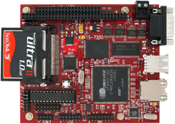
opted for was a TS-7200, an embedded ARM computer running Linux. This computer
comes with an ethernet port, 2 usb ports, 2 serial ports, 20 digital
I/O ports, and 8 analog input ports.
First off, I need a computer on the critter, a means for it to share a
wireless datastream with a camera, enough input/output ports to control the
motors, monitor the sensors, and any other features I might choose to add. It
also needs enough processing power to handle all of the interfaced
devices, and in the future, do all of its own map processing on board.
That's more than a simple microcontroller will be able to handle. What I
opted for was a TS-7200, an embedded ARM computer running Linux. This computer
comes with an ethernet port, 2 usb ports, 2 serial ports, 20 digital
I/O ports, and 8 analog input ports.
The distribution I'm using is Debian Sarge, although virtually any
distribution that supports the ARM9 platform should work on it, and
there's always the option to roll your own distribution if necessary,
although I don't forsee that as being the case here. The board itself,
without the optional CF card, has an even tinier linux distribution
on board. About 8 megs of space is available for programs and files.
Camera
 Now, I've got the computer and I can compile and run my software on it. I need
a webcam and a wireless interface. The wireless part was easy. The same
company that sold me the computer also sold me the usb WIFI dongle that
included linux drivers, so I was set to go there. The webcam was another
issue. I tried several different webcams, all of which worked on other
linux boxes. I was able to compile the drivers, but the cams refused to
work. I suspect the computer didn't provide enough current for the
cams to function. My options now were to either try a powered usb hub, all
of which seemed like they would require a lot of extra power to operate,
or find some other solution for the cam.
Now, I've got the computer and I can compile and run my software on it. I need
a webcam and a wireless interface. The wireless part was easy. The same
company that sold me the computer also sold me the usb WIFI dongle that
included linux drivers, so I was set to go there. The webcam was another
issue. I tried several different webcams, all of which worked on other
linux boxes. I was able to compile the drivers, but the cams refused to
work. I suspect the computer didn't provide enough current for the
cams to function. My options now were to either try a powered usb hub, all
of which seemed like they would require a lot of extra power to operate,
or find some other solution for the cam.
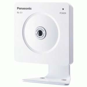
Seeing how the computer has an ethernet port, I decided instead to try an
IPcam, connected to the computer via a crossover cable (so a network hub
wasn't required). The camera I selected is a Panasonic BL-C1A. It costs anywhere from $70 to $110 and has a decent image in both light and dark conditions.
This let me use the computer as a router for the
webserver built into the IPcam, although I eventually wrote a small
cgi script to grab the image and rebroadcast it, so I could add extra
security to the process. The IPcam I used also has the benefit of using
much less power than a typical USB cam would, so it's not a major drain on
the limited power I have available.
Motors
 The next plan was to find suitable motors. This was not a trivial task.
I still haven't been entirely successful. The basic requirements for the
motors were that they work off 12V, geared to something where I get around
1 revolution per second, and have a shaft which will fit the hubs for
wheels. I wasn't concerned with exactly what the shaft size was, only
that I could find wheels, wheel hubs, and a motor to all match up. This
was far more difficult than you would think, considering the sheer volume
of different parts available. Even so, I still had to cheat a bit. The
shaft and bore on the hub are 6mm, but there's no screw or key on the
hub, so I had to resort to something more primitive.... superglue.
The motors I'm using also are not equipped to handle an encoder, so I can't
add odometry to the critter without finding new motors. However, I need
to start somewhere.
The next plan was to find suitable motors. This was not a trivial task.
I still haven't been entirely successful. The basic requirements for the
motors were that they work off 12V, geared to something where I get around
1 revolution per second, and have a shaft which will fit the hubs for
wheels. I wasn't concerned with exactly what the shaft size was, only
that I could find wheels, wheel hubs, and a motor to all match up. This
was far more difficult than you would think, considering the sheer volume
of different parts available. Even so, I still had to cheat a bit. The
shaft and bore on the hub are 6mm, but there's no screw or key on the
hub, so I had to resort to something more primitive.... superglue.
The motors I'm using also are not equipped to handle an encoder, so I can't
add odometry to the critter without finding new motors. However, I need
to start somewhere.
Once I got my motors, I had to design a drive system. Since the wheels would
attach directly to the shaft of the motors, at least I didn't need to
build a gearbox/train, but I still needed to decide on how I wanted the
wheels oriented. I opted for a 4 wheel differential drive system, with 4
motors... and that was a mistake. I was hopeful that the torque of the
motors would overcome the drag inherent in such a layout, but it still
takes far more effort to spin than it should, especially on carpet.
The next model will either be 2 motorized wheels + 1 caster, or 2 casters. 2 casters would be more stable, but it also means that one of the powered wheels
could be off of the floor, which would cause inaccuracies in odometry,
as well as make it difficult to manuver. The 3 wheel arrangement
would have stability problems unless most of the weight is kept in the triangle
between the three wheels.
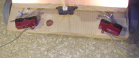
The Frame
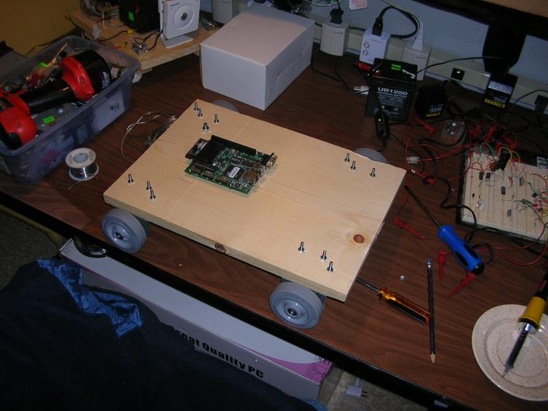 Although I investigated using plastic or metal for my frame, since this is a
prototype and will likely use something of a more permanant nature on the
next stage, I opted to go with wood. It's strong, light, and easy to
work with. It also warps over time, so it's not a long term solution, but
it'll work for the time being.
Although I investigated using plastic or metal for my frame, since this is a
prototype and will likely use something of a more permanant nature on the
next stage, I opted to go with wood. It's strong, light, and easy to
work with. It also warps over time, so it's not a long term solution, but
it'll work for the time being.
I found some brackets at the hardware store which, while somewhat
pliable, were still stiff enough to support the motors and the frame, so
I used those, drilled some holes to mount the motor and screwed them to
the base.
The next project was to design the H-bridge for the motors. This was
pretty simple once I obtained the right components and heatsinks. H-bridge
design and implementation is well covered concept, so I'm not going to
delve into it here.
Power
 For power, I'm using a 12V 5Ah gelcell. I'm currently using a 9V linear
regulator off the 12V to power the camera, and I then feed a 5V linear
regulator off of the 9V to power the computer. The motors take the
raw 12V straight from the battery. The obvious problem here is that
linear regulators are horribly wasteful. I lose 60% of my battery
potential just by using them. I've found some switching regulators that
come in the same packaging as a 7805 and they look promising, so I have
plans to replace at least the 5V regulator with a switching model to cut
down on the power waste. The camera doesn't use much current, and a 9V off of 12V isn't a huge loss anyway, so I'll likely keep that regulator as is.
For power, I'm using a 12V 5Ah gelcell. I'm currently using a 9V linear
regulator off the 12V to power the camera, and I then feed a 5V linear
regulator off of the 9V to power the computer. The motors take the
raw 12V straight from the battery. The obvious problem here is that
linear regulators are horribly wasteful. I lose 60% of my battery
potential just by using them. I've found some switching regulators that
come in the same packaging as a 7805 and they look promising, so I have
plans to replace at least the 5V regulator with a switching model to cut
down on the power waste. The camera doesn't use much current, and a 9V off of 12V isn't a huge loss anyway, so I'll likely keep that regulator as is.
Once the change has been made to a 5V switching regulator as opposed to the
current linear one, the uptime for the critter should extend to about 10
hours on a full charge. That almost reaches my 12 hour goal and exceeds the
full recharge time of a spare battery.
Lights
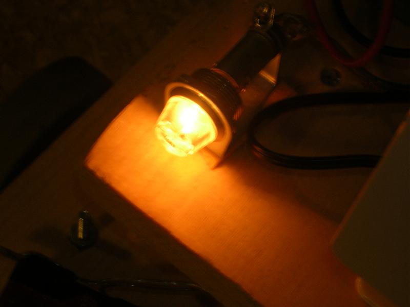 The lights on the critter are little 12V incandescent lamps.... which suck.
If it's pitch black, and you're 1 ft away from something, you can see the
light, but it does little to illuminate the area. They also use a lot of
power. I'm going to use a white LED array instead, and maybe scavenge some a
flashlight reflector to focus the light ahead more.
The lights on the critter are little 12V incandescent lamps.... which suck.
If it's pitch black, and you're 1 ft away from something, you can see the
light, but it does little to illuminate the area. They also use a lot of
power. I'm going to use a white LED array instead, and maybe scavenge some a
flashlight reflector to focus the light ahead more.
Sensors
 Currently, I have one IR rangefinder and 2 limit switches, both for proximity
detection. They are far from foolproof, but they do at least prevent quite
a few collisions. More coverage will be needed yet though. The infrared
rangefinder has a range of about 30 inches, although all I do is constantly
poll the sensor to see if it's currently 5 inches or less away from an object.
If so, the critter is immediately commanded to override any current command
and reverse at full speed and maintain this mode until the gap is greater
than 5 inches. This also will allow you (or a pet) to move the critter
simply by holding an object directly in front of it. The limit switches
engage whenever they are tripped. They're not perfect for the job, a
sensitive "whisker" would work better, but they do in a pinch. They will
detect a collision that is outside of the field of view of the IR sensor, which
lets face it, is pretty narrow. A chair leg or something thin can still get
between the sensors, but anything larger will get hit by one of them at
least. When the limit switch gets engaged, the critter will "shake". It
will move forward, backwards, turn left, turn right, in a random sequence
until the switch is no longer engaged. The reason for doing this is because
both switches are on the same input circuit and I don't know which one has
been tripped. Eventually I'll set it up so any switch can individually
trip a sensor, and knowing which switch did it, the appropriate action can be taken to reverse the process.
Currently, I have one IR rangefinder and 2 limit switches, both for proximity
detection. They are far from foolproof, but they do at least prevent quite
a few collisions. More coverage will be needed yet though. The infrared
rangefinder has a range of about 30 inches, although all I do is constantly
poll the sensor to see if it's currently 5 inches or less away from an object.
If so, the critter is immediately commanded to override any current command
and reverse at full speed and maintain this mode until the gap is greater
than 5 inches. This also will allow you (or a pet) to move the critter
simply by holding an object directly in front of it. The limit switches
engage whenever they are tripped. They're not perfect for the job, a
sensitive "whisker" would work better, but they do in a pinch. They will
detect a collision that is outside of the field of view of the IR sensor, which
lets face it, is pretty narrow. A chair leg or something thin can still get
between the sensors, but anything larger will get hit by one of them at
least. When the limit switch gets engaged, the critter will "shake". It
will move forward, backwards, turn left, turn right, in a random sequence
until the switch is no longer engaged. The reason for doing this is because
both switches are on the same input circuit and I don't know which one has
been tripped. Eventually I'll set it up so any switch can individually
trip a sensor, and knowing which switch did it, the appropriate action can be taken to reverse the process.
Horn
I have a buzzer that makes a great horn... however, it also buzzes anytime the
wheels are engaged, which is quite annoying and pointless. I suspect the
feedback from the motor coils is whats's causing it, but I have yet to
come up with a filter. Probably a diode and capacitors.
Software
 The software was actually pretty simple.
As mentioned earlier, the computer is running Debian Linux. Other than
drivers included with the purchase of the computer and startup scripts, I haven't had to make
any other changes to the operating system.
The software was actually pretty simple.
As mentioned earlier, the computer is running Debian Linux. Other than
drivers included with the purchase of the computer and startup scripts, I haven't had to make
any other changes to the operating system.
For the operation of the critter, I'm using lampmaster. I already had
code in place to control the original RC cars, and I only
needed to make a few modifications to support the motor control on the TS-7200.
Right now,
the critter is command oriented, except when one of the proximity
sensors is triggered, and it then takes a reactive action.
Current Problems
Although this page has so far mentioned some of the shortcomings, there are
some additional problems that have cropped up several times since deploymnet.
- The huge heatsinks on the voltage regulators aren't secured, and therefore
will vibrate around a bit while the critter is moving. Over time, this
causes the contacts to come loose and requires me to resolder the
connections, or possibly replace the regulator. Since I plan to switch to
a switching regulator that shouldn't require a heatsink, this problem
shoudl be eliminated.
-
- Radio deadzones are also a problem, but the solution, while simple in
concept, is problematic as well. The critter can know if it has lost
its signal easily enough. Either it can try to contact a local host to
see if it can establish a connection, or it can simply monitor the signal
level directly. The problem is, once the critter knows it's in the dark,
how should it respond? Without a decent way to navigate, it can't reliably
backtrack. Once odometry and rangefinder sweeps are implemented, this
shouldn't be much of an issue anymore.
- The critter base is wider than the camera angle can cover. Therefore,
while it looks like you're going to successfully drive past an object, you're
actually still on a collision course with it. The camera lens probably can't
be swapped out easily, but once the rangefinder sweep is in place, a
visual representation of the surrounding environment with the critter image
overlayed SHOULD assist in making manual navigation easier.
Future Plans
While my ultimate ambitions for this toy are rather lofty, short term, I
have several issues I need to resolve and several features I need to
implement. These will involve multiple stages.
Other Stages
-
For Stage 2, I won't be concentrating on aesthetics, but I need to have the critter be
fully mobile, wheels need encoders, and it needs to be able to map-match
and self navigate.
-
Stage 3 will be the stage where all parts are designed and developed to have
a professional look and feel to them. At this point, it can be sold, either
assembled or in kit form, but will not likely be at a price that would have
many takers.
-
Stage 4 will consist of cost cutting processes to make the critter affordable
for the general public, if that's a realistic goal.
Wheel encoders
Wheel encoders are absolutely necessary for the purpose of maintaining
odometry. The critter needs to know how far it has travelled and in
what direction.
Rangefinding scan
A servo will be set up with a combination of a sonar and IR scan, to provide
a representation of the room ahead (and perhaps behind). This will require
a PWM controller for the servo, as well as software to interpret the most
accurate of the readings from the sweep. IR tends to be more accurate, but
with a shorter range than sonar. Sonar, however, is better at picking
up chair legs. The scanning hardware itself needs to be free of obstructions,
but at the same time needs to be protected from collisions with obstacles.
Mapping Software
I need to develop software that takes a series of scans and uses that data to determine
the location of the critter on a map. SLAM mapping will be a future project,
but for now, simple map matching will work.
Docking Station
Being able to locate and engage a docking station will greatly extend the
operational life of the critter without operator intervention. The ability
to find the location of the docking station on the map is important to this
feature.
Commercial Possibilities
The "Critter" name is based on the potential for a commercial market. It's
also pragmatic. What else do I call it, after all? It's not a car, due
to it's 4-axle and differential drive, it's not really a robot right now,
as it's not presently autonomous. I call it a critter as I can envision
selling a toy with a unique critter body... something like a huge cute
mouse, only one that's internet capable AND autonomous.
Price Point
To sell as a toy, the unit will have to be priced for less than $300. That
isn't very likely, at least without a massive amount of sales, as the
computer and camera alone approach that figure, and that's even before all
the mechanical parts, sensors, and assembly labor costs. $500 would currently
be about the break-even point. That's still feasible for a hobby-market.
Those that purchase preassembled robots will spend that much with no problem,
but by missing the toy market, the chances for huge sales are gone.
Reaching the $300 price point will require an extensive amount of R&D,
a higher cost for assembly labor, and a large bulk purchase (and possibly
custom design) of the computers, cam, and circuit boards.
- Motors without the gearhead are pretty inexpensive. This means I'll need to develop a gearbox for the motors. This is ideal in many ways, as I will have better control over the desired torque and shaft sizes, but it requires a precision job which will likely need to be outsourced. Encoders will also need to be
developed in-house as prebuilt ones are too expensive.
- The auxiliary circuitry will need to be a PC/104 compatible attachment.
This allows for an unlimited amount of I/O ports, interrupts, etc. However,
it will greatly extend the design and testing phase to develop all the
necessary circuits.
- The body of the critter can be created to provide a housing for the
camera, so the camera itself need not have a shell of its own, only the
actual circuit board is needed (if I go with the IPcam option). It's possible,
with a bulk purchase, to save a few bucks on each camera without the housing, or more if we
can take advantage of a bulk discount. Although the camera currently in
use is one of the least expensive options available, there might be others
as well that could be even less expensive.
- A custom design of the TS-7200 should be investigated to determine if
eliminating any unneeded features could cut the costs of the purchase.
Obviously a bulk purchase of the computers (in excess of 100) would save
quite a bit.
Marketing
Of course, once I have a product to sell, I'll actually need to sell it.
Who would this be targeted to? What age range, etc. These are questions
to mostly answer later, however there is little point in investing a lot
of resources and raising the price point for features nobody would ever
be interested in.
One target is toward the hacker market. Although I won't support it under
warranty, I want to make it as easy as possible for interested parties to
modify the unit for their own purposes. I will be sure to open source all
software used on the Critter as well as provide extensive documentation on
doing development projects with it.
|
| 200 mhz ARM9 CPU | 32 Megs Ram |
| 1 10/100 ethernet | 2 USB 2.0 |
| 1 CF socket | 2 COM ports |
| 20 Digital I/O lines | 8 analog inputs |
| 5V @ 400mA | 3.8" x 4.5" |
H-Bridge and Power circuits
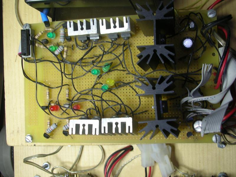
This circuit will eventually take up far less space. The huge heatsinks
are for the 7805 and 7809 regulators. Switching regulators will likely not
require them. The rest of the circuit can be optimized by a better board design.
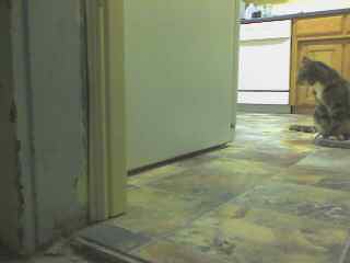
Obstacle Avoidance
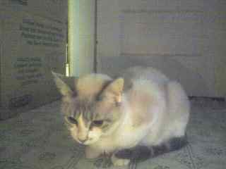
Large objects, like cats, are easy for the sensors to detect, and therefore prevent collisions. Smaller objects like
chair legs will require a larger sensor net to ensure detection.
Other obstacles
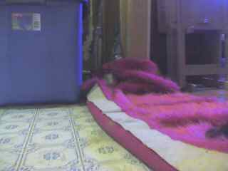
The critter needs to be able to navigate over, through, or around a number
of obstacles for which collisions are not a concern. Carpet, rugs, clothing,
room thresholds, small steps, etc. The motors have to be powerful enough to
overcome slight obstacles such as these. Spinning on carpet is very difficult
as it creates a lot of friction.
Radio Interference
Another enemy of the critter is the loss of radio signal for the wireless
network. If a stable connection can't be established, it can't receive
commands, and it can't send video. From the server side, it would appear
that the critter has died. The critter must have enough programming smarts
to successfully navigate out of any such radio blind spot, or navigate back
within range if the roaming area is large enough to lose contact. Large
metal objects, such as refridgerators, dishwashers, ovens, and metal
furniture that lie in the path between the critter and the access point
will cause signal degradation and can be the cause of a radio blind spot.
Human Related Hazards
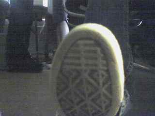
Of course, cats aren't the only potential hazard to the critter. Since it
sorta has a mind of its own, it's possible it might end up somewhere it was
not expected, and therefore get stepped on, kicked, or otherwise manhandled.
This can be potentially damaging to the critter, and maybe even the human.
First off, the critter needs to be robust enough to handle getting
momentarily stepped on or kicked without breaking into a million pieces.
Secondly, the critter should make noise and attempt to escape if a massive
object is suddenly moving toward or over it, hopefully to prevent getting
trampled.
|