
| LCARS | test |
|
|||||
|
|||||||
 | ||||
|
Please note, the RC car described in this document no longer exists. This
document remains only for historical purposes. There have been 4 different
controllable vehicles over the years. The first two were converted RC Cars,
the third was a converted RC tank, and the current incarnation is a robotic
critter which I have built from scratch. Please visit the main page and
inquire about playing with it. Thank you.
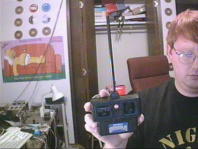
When I interfaced the first RC Car I didn't post detailed instructions or even take pictures. This time I'm doing things in a much more detailed and professional way, and allowing others a chance to see the project step by step. There are two stages to this project. Modding the remote, and modding the car. Although both are necessary for the full effect, they can be done separately and still end up with a useful end result. We will start with the remote.
The Remote
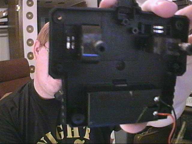
First a little info about how the remote operates. Each of the toggles is a double pole, triple throw switch. When you push the drive lever up to make the car go forward, two small conductors connect two pairs of contacts on the circuit board. Moving the lever in the opposite direction makes two separate contacts, although one of those contacts is common between all four of the lever positions. When the levers are in their center state, no contact is made. Unscrew the four screws on the back of the remote and remove the cover and you'll see something similar to this:
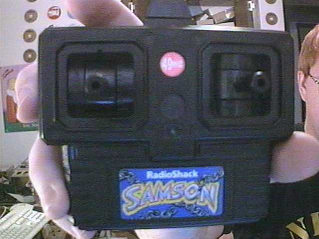
Inside the Remote. AKA: Voiding your warranty
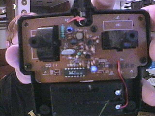
Remove the screw attaching the wire to the antenna, then you should be able to lift the circuit board over the levers and look at the back side.
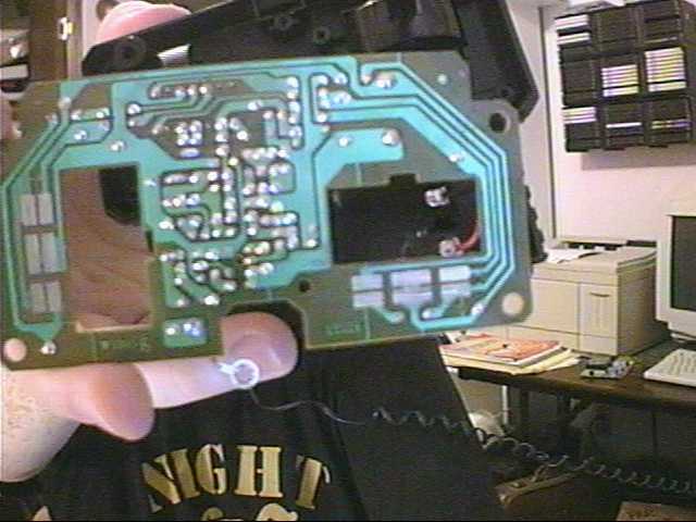
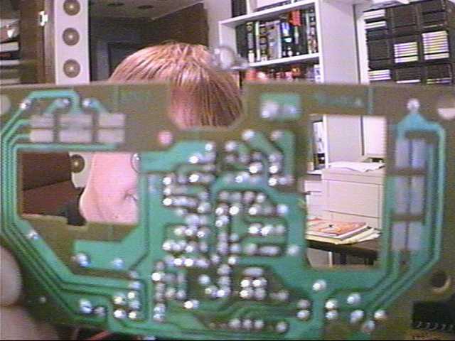
The other side of the circuit board
The back of the remote. Levers and Sliders
Circuit Board up close
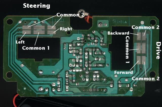
Labeled Circuit Board
If you look at the board, there are two sets of 6 contacts on the board. This is where the sliders make contact. All contacts labeled Common 2 are electrically common, as are all the Common 1 contacts. To move the car forward, a connection will be made between the contact labeled forward and common 1, and another connection will be made between common 1 and common 2. The same method is used for the other three possible actions. How you wire this up depends on if you want the remote to be useable as a manual remote after modding. If there is no concern about manual use afterwards, wires can be soldered directly to the large contacts. To maintain the use afterwards, the contacts need to maintain clear and wires need to stay out of the way. Therefore, its best to find contacts on the component side that electrically match the control contacts. The 6 wires needed then need to run to the relay board.
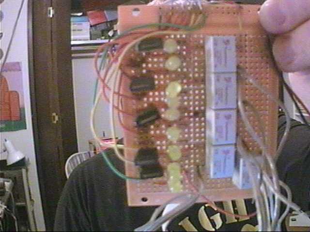
Relay board
The Relay board is composed of 5 relay circuits, the same I have controlling the office lamp. Since I don't need much power, I can get by with smaller relays. I will include a schematic for the board in the future, bit its not too tough. Basically, each of the 5 relays is controlled via one of the data pins from a parallel port.
The CarNow on to the second stage. The car itself.
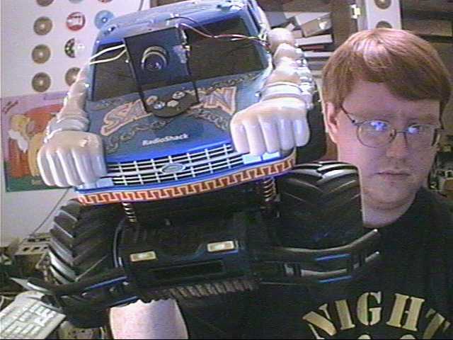
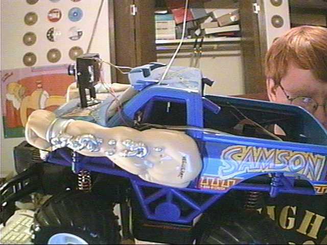
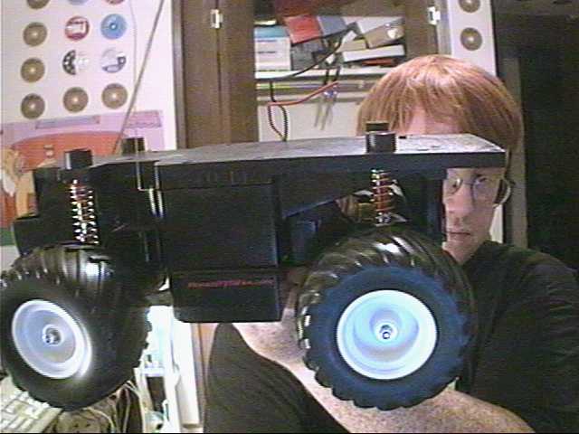
The Car
As you can see I have the cam mounted to the hood of the truck. I've later decided to remove the entire frame and just use the flat platform, as you'll see later. However, I didn't consider this possibility until after I disassembled it. And what a chore THAT turned out to be. It was a very well put together little bugger.
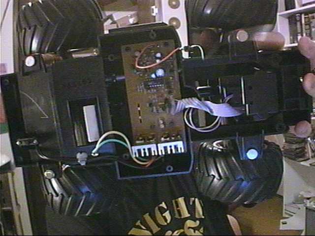
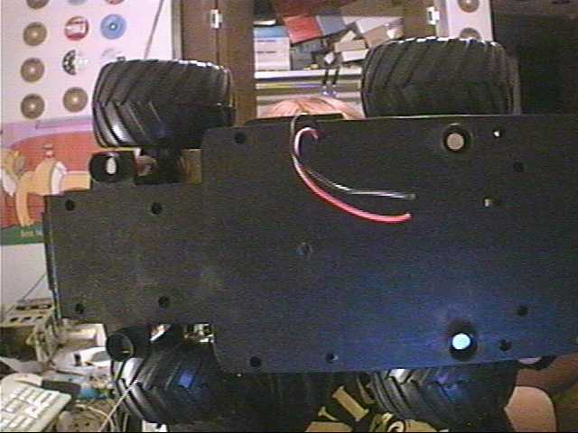
40 screws later, the frame and platform is off.
Not much to see here, but the bottom of the truck is where the battery would normally be placed, and there's a power cable under there for it. Well, since we will have a rather LARGE battery on top already, there's no sense in adding a second battery. The car can just use power from the gelcell. To do this, we need to cut the connector off the plug under the car and pull the wires through the bottom. Then take the platform of the car that you've removed and drill a hole wide enough for the two power wires (or just widen one of the screw-holes you won't be using any longer). Run those wires through the hole and replace the platform. You should now have something like this:
It's Starting to Look Like Something.
Notice the two wires sticking up from the base, those are the power wires. Now we need to get the battery hooked up.
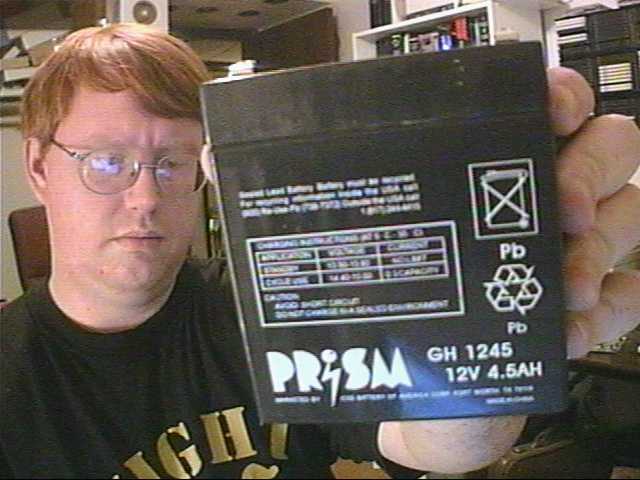
The Battery
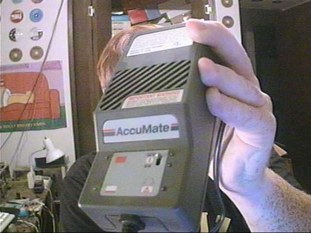
The Charger
A Power Cable
The Battery is a 12 Volt, 4.5 Amp Hour Gel-Cell. It will run the camera and transmitter for 21 hours and recharge fully in about an hour. I suspect I will have two batteries that I will swap out every 12 hours. This will allow me to also run Infrared headlights and perhaps some other features. The battery is charged using a special battery charger for lead acid batteries. Normal wallwarts won't work, as they'll overcharge the battery. So get a real charger. To wire the battery to the car, first take one of the cables with the plugs on the ends, and cut it in half. Take the female end and wire it to the battery. This will allow you to plug either the car or the charger into it. Take the two tabs and use them to seal the wires to the battery. Pay attention to polarity. The wire colors will match up. You might want to solder the wire onto the battery to be extra secure. You won't need to remove it before the battery dies, so there's no concerns of permanancy here. Take the male end and wire it to the power wires for the car. Like the battery, the wire colors will match up (assuming the car's colors were Red/Black). You can now plug the car's power plug into the battery and the car will have power. Turn it on and grab the remote and see if it works. Of course, as soon as it moves, the battery will fly off the car. For testing purposes, I'm just taping the battery to the car's platform.
SpeedThe next important issue is speed. The RC car is probably quite capable of achieving adaquate speed to cause damage if it hits a solid surface (a wall for instance). While the car itself can probably handle it, remember, we are also mounting a camera on top of the car and the camera is far more delicate. Therefore, you want to force the car to not go faster than a certain velocity. The easiest way to do this (and its already in the code) is to simply put a delay between the time you make the contact and the time you stop it. A delay of 500 ms is a nice speed. Of course you may want different speeds. That is completely up to you.
CameraThe camera part itself was much easier, although more expensive. First, you'll need a capture card or a Snappy or some video input device that will take an RCA jack as input. Then you will need to purchase a transmitter/receiver kit that can send/recieve video and a small, low powered camera. I purchased both these items from MatCo. The model numbers there are CNL-100 and ASK-2000TR. I also purchased the enclosure for the camera, model number A-300. You may have to browse the pages a bit to find the actual model numbers. They don't all appear on top. Please note that I am in no way affiliated with MatCo, I simply found that their products were the least expensive for what I needed to do and so far I have had no problems with the products. The receiver has a female RCA jack for video out. Take any RCA cable and hook that puppy up to your capture card. Take the camera, which has 4 wires. READ THE INSTRUCTIONS THAT COME WITH THE CAMERA. They are vague, but they tell you which wires do what. Two of the wires are for power, and the other two are for the video signal. The video wires can be directly wired to an RCA plug, which can then be plugged into the transmitter. Then go to radio shack and find yourself a power adapter plug which fits the transmitter. Wire the camera's power wires to this plug as well as another set of wires which will then go to your power source. Plug it into the transmitter and now you have power to the camera and transmitter. |